Appearance
Hardware reference
The IMOCA Keel Management v2 system is made of three distinct units.
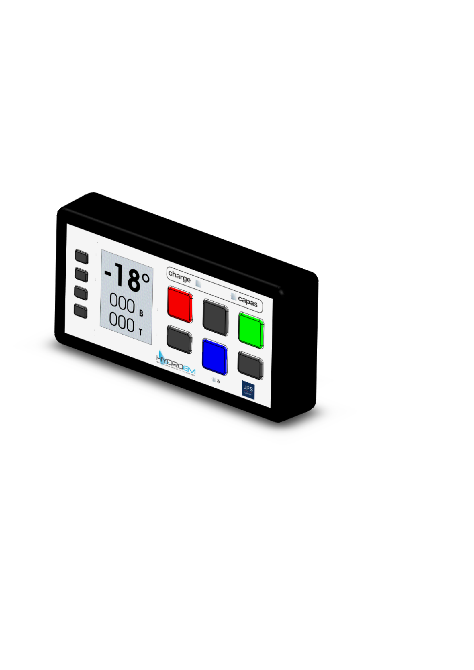
Façade 2024
The Façade 2024 is the primary user interface. LCD display showing keel angle and chamber pressures, plus six push-buttons (red, gray, green, blue, plus arrow keys) and an OK / SET row used for parameter editing.
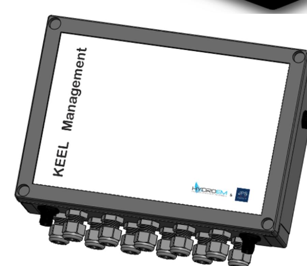
KEEL Management box
Central controller of the system. Drives the hydraulic solenoid valves, reads the position and pressure sensors, runs the calibration logic and emits the system state on the CAN bus. M12 connectors on the bottom carry the CAN buses, sensors and valve outputs.
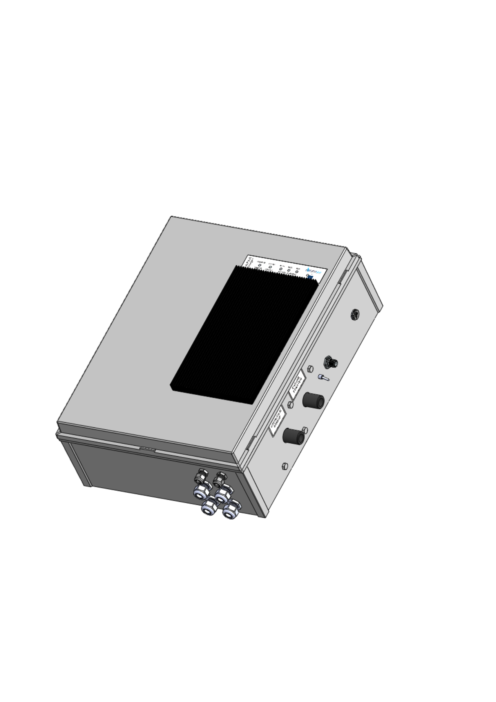
Supercapacitor cabinet
Energy buffer of the system. Limits the peak current drawn from the boat batteries by sourcing the high-current pulses from a supercapacitor bank, charged at a configurable rate. Hosts the charger, the front-panel LEDs and the rotary current selector. See the Supercapacitor page for details.
Sensors
| Sensor | Reference | Output | Range | Wiring |
|---|---|---|---|---|
| Cylinder rod position | IFM PK7521 | 4–20 mA | full stroke | brown = +V, black = signal, blue = −V |
| Chamber pressure (port & starboard) | IFM PU8500 | 0.5–4.5 V | 0–400 bar | brown = +V, white = signal, black = max output, blue = −V |
Actuators
| Output | Type | Function |
|---|---|---|
EV REL PORT | Solenoid valve | Releases the port chamber pressure |
EV REL STRB | Solenoid valve | Releases the starboard chamber pressure |
EV PORT | Solenoid valve | Pressurises the port chamber for a port-side movement |
EV STRB | Solenoid valve | Pressurises the starboard chamber for a starboard-side movement |
RELAIS POMPE | Power relay | Engages the hydraulic pump motor |
Management board
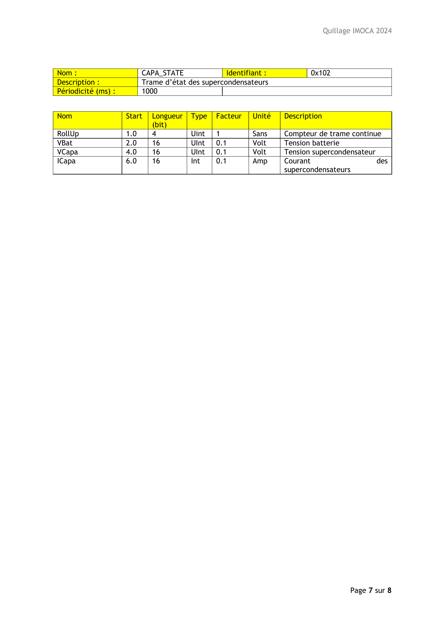
For reference, the management board layout (from the CAN protocol document):