
Appearance
IMOCA — Keel Management v2
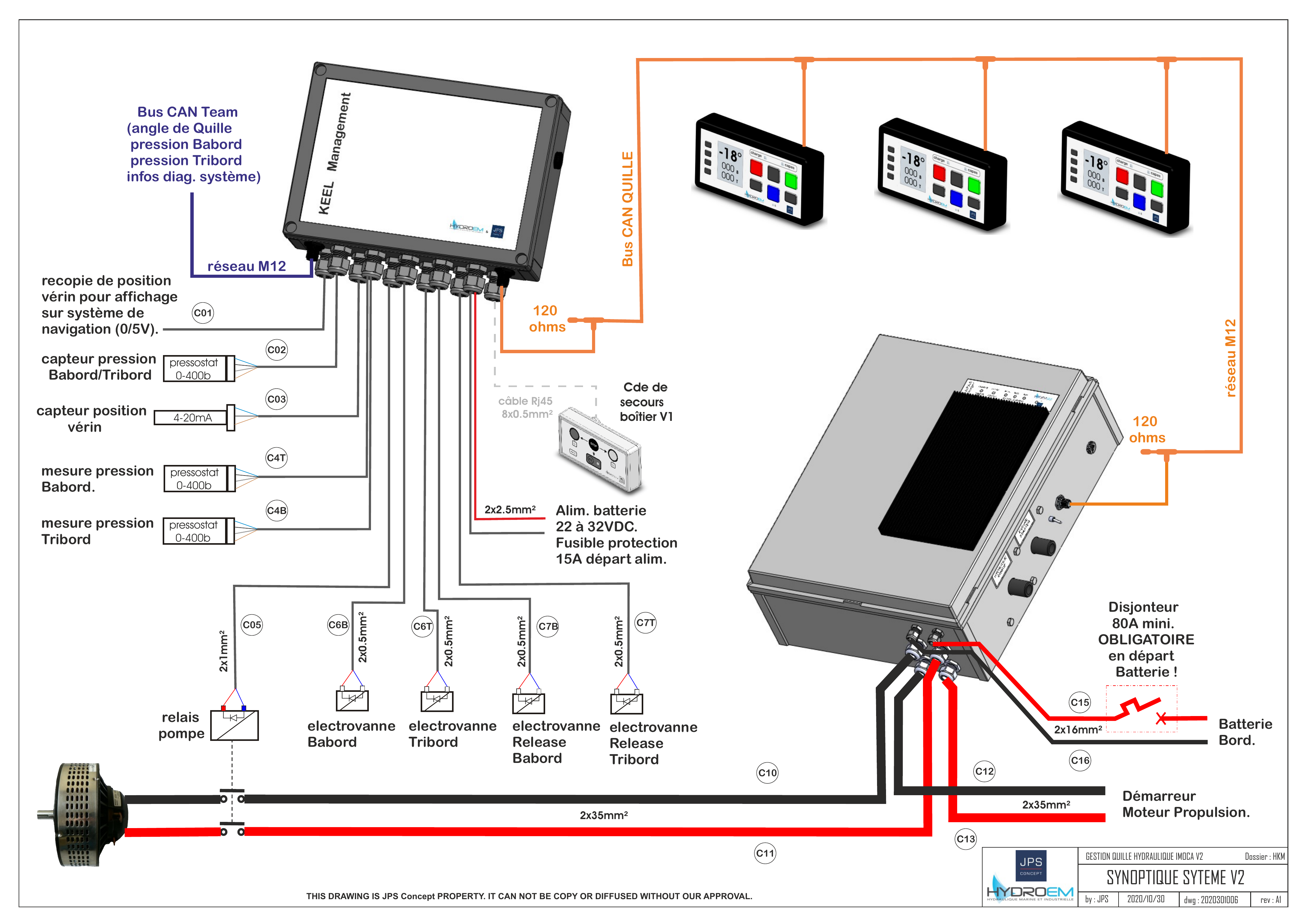
The IMOCA Keel Management v2 system controls the canting keel of an IMOCA 60. It is a joint product of HYDROEM, JPS-Concept and L2C-tronic, integrated by MUXEN.
Subsystems
The system is built from four distinct units:
- Façade 2024 — primary user interface. LCD display showing keel angle and chamber pressures, plus a six-button control panel. Used for movements, calibration and parameter setup.
- KEEL Management box — central controller. Drives the hydraulic solenoid valves, reads sensors, runs the calibration logic, and emits the system state on the CAN bus.
- Supercapacitor cabinet — energy buffer. Limits the peak current drawn from the boat batteries during keel movements by sourcing it from a supercapacitor bank charged at a configurable rate.
- Façade 2020 — legacy interface kept as a backup. Three large buttons (Port / STOP / Starboard) plus a Release button.
Documentation
- Installation & wiring — power, CAN bus, sensors, valves, calibration procedure.
- Operation — display, movement modes (Release / Main / Incremental), Release Assist.
- Parameters & error codes — Set quille, Set Alim, Affichage, error reference.
- Supercapacitor — charger, current selector, LED indicators.
- CAN protocol — bus parameters, M12 pinout, frame definitions.
- Hardware reference — control box, cabinet, sensors and actuators.
Source files
Original manufacturer documents (HYDROEM / JPS-Concept / L2C-tronic):
| File | Description |
|---|---|
| QuillageImoca2024_ManuelUtilisateur.pdf | User manual (FR) |
| QuillageImoca2024_ManuelUtilisateur.docx | User manual — Word source |
| QuillageImoca2024_DescriptionCanEquipe.pdf | CAN protocol specification |
| GESTION QUILLE V2.PDF | System synoptic |
| GESTION QUILLAGE HKM V2 A1.pdf | HKM v2 architecture diagram |
| RAC GESTION QUILLAGE V2 A0.pdf | Full wiring schematic |
| BOITIER CDE IMOCA V2.PDF | Control box render |
| ARMOIRE V2-COM.PDF | Electrical cabinet render |
| Présentation Système Quillage V2.pptx | System presentation |