Appearance
Installation & wiring
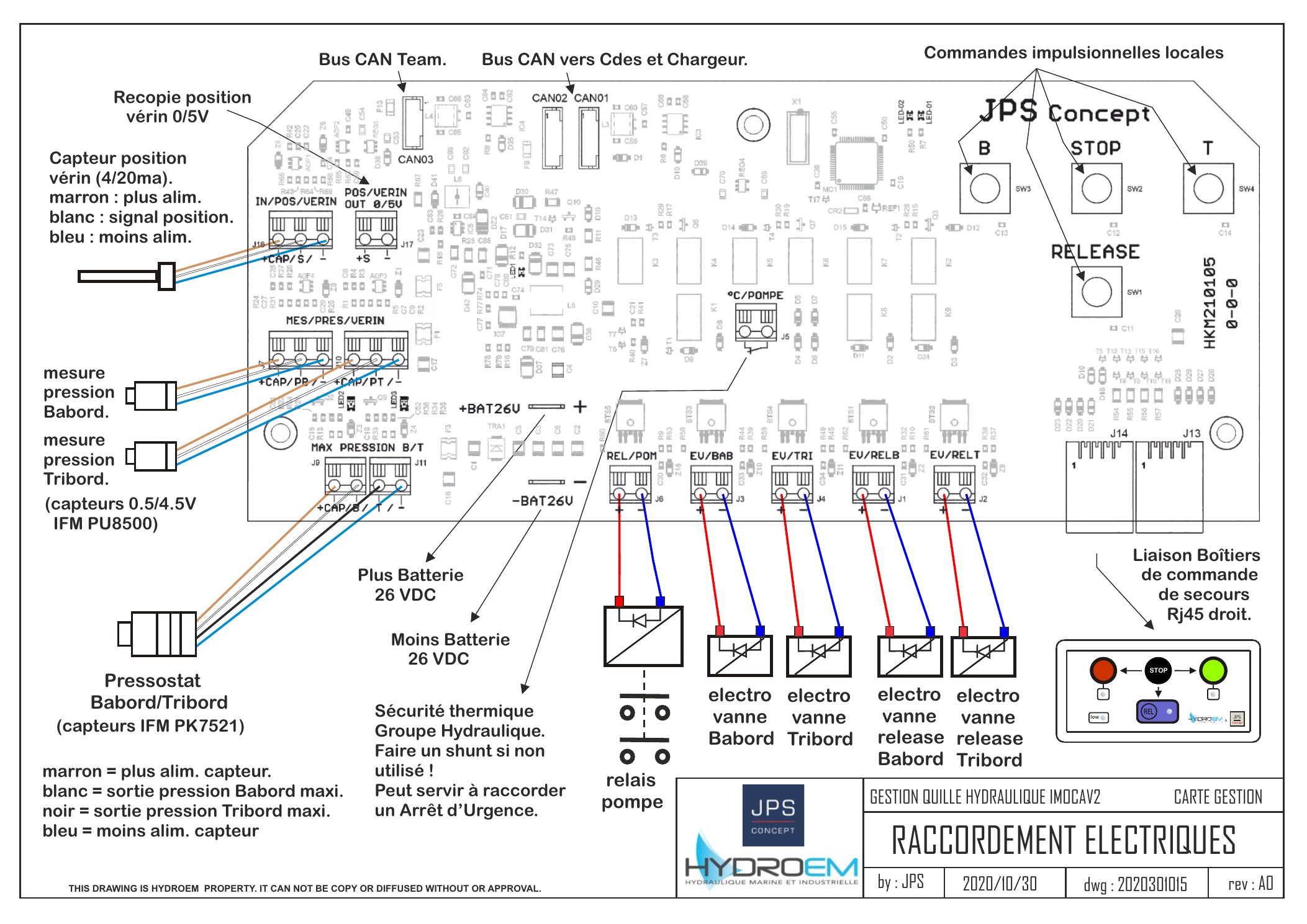
This page covers powering, wiring and calibrating a fresh IMOCA Keel Management v2 install. The full management board schematic is available at the bottom of the page.
Power
| Item | Value |
|---|---|
| Battery voltage | 22 to 32 VDC (nominal 26 VDC) |
| Power supply fuse (control) | 15 A |
| Battery feed cable | 2 × 35 mm² |
| Auxiliary power | 2 × 16 mm² |
| Pump motor return | 2 × 1 mm² |
Mandatory safety
An 80 A minimum circuit breaker is mandatory on the battery feed of the cabinet. Never bypass it.
CAN buses
The system uses two CAN buses, both terminated in M12 NMEA-2000 connectors:
- Bus CAN Quille — links the KEEL Management box to the façades (2024 and 2020). Carries keel angle, chamber pressures, system diagnostics.
- Bus CAN Team — connects the cabinet to the boat's navigation system for display recopy and remote diagnostics.
The KEEL Management box does not include built-in 120 Ω terminations. The installer must add two 120 Ω terminating plugs, one at each end of every bus segment.
See the CAN protocol page for the full M12 pinout and frame definitions.
Sensors
| Sensor | Reference | Output | Wired to |
|---|---|---|---|
| Keel position (cylinder rod) | IFM PK7521 | 4–20 mA | POS VERIN input on the management board |
| Port chamber pressure | IFM PU8500 | 0.5–4.5 V | MES PRESSION B/T (port) |
| Starboard chamber pressure | IFM PU8500 | 0.5–4.5 V | MES PRESSION B/T (starboard) |
Each sensor uses a 2 × 0.5 mm² shielded cable. Color code on the IFM PU8500 leads: brown = +V supply, white = signal, blue = −V (GND), black = port/starboard pressure max output.
A RECOPIE POSITION 0/5 V output is also exposed for the boat's display system.
Solenoid valves
Five electrohydraulic outputs are driven by the management board, each on 2 × 0.5 mm²:
| Output | Function |
|---|---|
EV REL PORT | Release valve, port side |
EV REL STRB | Release valve, starboard side |
EV PORT | Movement valve, port side |
EV STRB | Movement valve, starboard side |
RELAIS POMPE | Hydraulic pump motor relay |
A thermal cutout of the hydraulic group is wired to the dedicated security input. If the group has no thermal protection, install a shunt on this input — the system will refuse to move otherwise.
Local commands
The management board exposes a local command interface (Port / STOP / Starboard buttons + a Release button) for emergency operation when no façade is reachable. A secondary boîtier V1 can be plugged in over a straight RJ45 link as a remote backup.
Calibration
Once the system is wired and powered, calibrate the keel angle. The procedure walks the keel from one extreme to the other and records the absolute angle at each end stop.
Clearance check
During calibration the keel will swing from one side to the other. Make sure there is enough clearance around the boat and around the mast at all times.
- From the home screen press OK then SET to enter the calibration procedure.
- Press the red button — the keel moves to port until it reaches the pressure stop.
- Use ▲ / ▼ to enter the actual measured port-side angle, then SET.
- Press the green button — the keel moves to starboard until it reaches the pressure stop.
- Use ▲ / ▼ to enter the actual measured starboard-side angle, then SET.
- Press the blue button — the system enters Release and the keel returns to 0° by gravity.
- Once at the centre position, use ▲ / ▼ to enter the measured 0° reference, then SET.
- The system reboots and is ready for use.
Stuck at 0°
If gravity is not enough to bring the keel back to 0° at step 6, press STOP to skip to step 7.
Wiring schematics