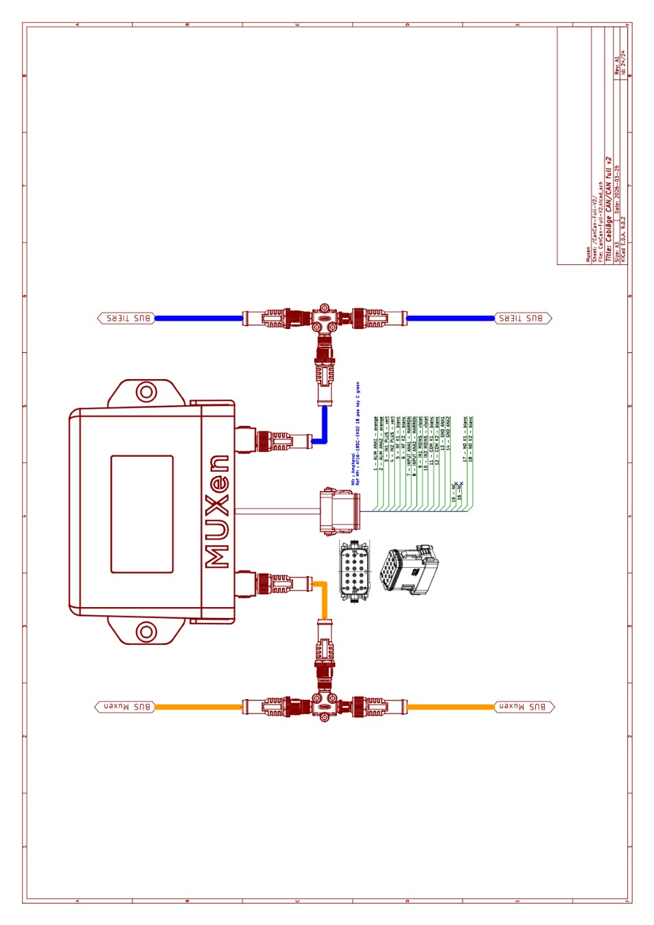
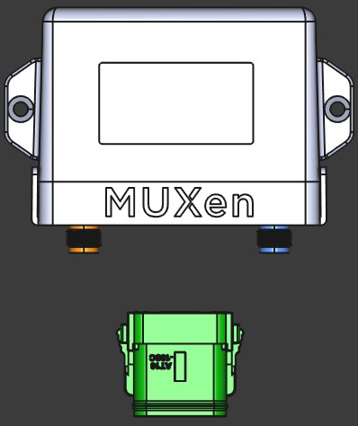
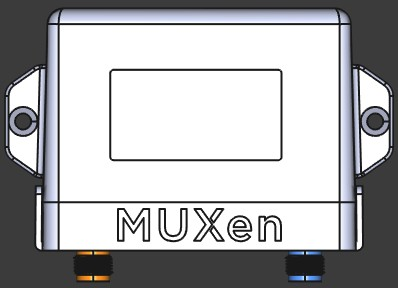
Appearance
CAN-CAN
The CAN-CAN is a communication gateway between the MUXEN network and a third-party CAN bus network. It is available in two versions: Basic and Full. The Full version adds an analog/digital I/O block usable from any MUXEN multiplexing rule.
This page is the product data: connectors, pinouts, electrical and mechanical figures. What the box does is decided by the firmware loaded into it — see the CanCan gateways overview for the catalogue, and each application's own manual for wiring and commissioning.
Supported third-party networks
| Network | Manual |
|---|---|
| NMEA 2000 (Victron, MG, Arco Zeus, Vetus) | NMEA 2000 gateway |
| J1939 bus (Fischer Panda and Cummins Onan gensets) | J1939 gateway |
| Scheiber wireless / battery-less network | Scheiber gateway |
| Aquabase watermaker proprietary bus | Aquabase gateway |
| Eco Sistems watermaker proprietary bus | Eco Sistems gateway |
| Bell Marine electric propulsion | Bell Marine gateway |
| A second MUXEN segment | Bus extender |
Versions
| Feature | Basic | Full |
|---|---|---|
| MUXEN connector (orange) | ✓ | ✓ |
| Third-party CAN connector (blue) | ✓ | ✓ |
| I/O connector (green, Amphenol AT16) | — | ✓ |
The Full version exposes:
- 2 × analog inputs 0–5 V (with sensor power supply)
- 2 × galvanically isolated digital inputs
- 2 × relay outputs (CO / NO / NC)
Electrical characteristics
MUXEN connector (orange)
Standard micro-C M12, 5 pins.
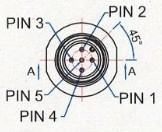
| Pin | Signal |
|---|---|
| 1 | wake-up |
| 2 | Power |
| 3 | GND |
| 4 | CAN High |
| 5 | CAN Low |
| Parameter | Description | Min | Typ | Max | Unit |
|---|---|---|---|---|---|
| Valim | Supply range (from MUXEN bus) | 9 | 12 | 14.5 | V |
| Ialim | CAN-CAN current draw | — | 15 | 20 | mA |
Third-party connector (blue)
Standard micro-C M12, 5 pins.
| Pin | Signal |
|---|---|
| 1 | NC |
| 2 | Power output |
| 3 | GND |
| 4 | CAN High |
| 5 | CAN Low |
| Parameter | Description | Min | Typ | Max | Unit |
|---|---|---|---|---|---|
| Valim_out | Output supply range (from MUXEN bus) | 9 | 12 | 14.5 | V |
| Ialim_out | Maximum output supply current | — | — | 500 | mA |
| Bus speed | Maximum third-party CAN bus speed (configurable) | — | — | 1 | Mbit/s |
I/O connector (Full version only)
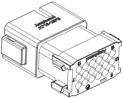
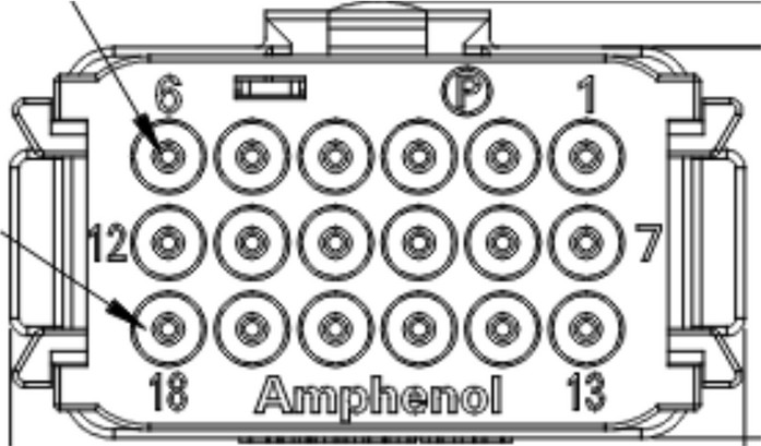
Connector (CAN-CAN side) — Amphenol LTD, ref. AT16-18SC-EK02.
Mating connector — Amphenol LTD, ref. AT16-18PC-EK02.
Contacts:
| Reference | Wire range |
|---|---|
AT60-14-0122 | 14–18 AWG |
AT60-16-0122 | 16–18 AWG |
AT60-16-0622 | 16–20 AWG |
AT60-16-0822 | 20–22 AWG |
Sealing plug for unused pins: A114017.
| Pin | Signal | Pin | Signal |
|---|---|---|---|
| 1 | ALIM ANA 1 | 10 | IN 2 − |
| 2 | ALIM ANA 2 | 11 | COM K1 |
| 3 | IN 1 + | 12 | COM K2 |
| 4 | IN 2 + | 13 | GND ANA 1 |
| 5 | NF K1 | 14 | GND ANA 2 |
| 6 | NF K2 | 15 | NC |
| 7 | IN ANA 1 | 16 | NC |
| 8 | IN ANA 2 | 17 | NO K1 |
| 9 | IN 1 − | 18 | NO K2 |
| Parameter | Description | Min | Typ | Max | Unit |
|---|---|---|---|---|---|
| Valim_ana_xx | Analog sensor power output | — | 5 | — | V |
| Ialim_ana_xx | Maximum analog supply output current | — | — | 100 | mA |
| Vin_ana_xx | Analog input voltage range | 0 | — | 5 | V |
| Vinx_max | Maximum voltage between IN X + and IN X − | — | — | 12 | V |
| Vinx_th | Digital input switching threshold | 5.5 | — | — | V |
| Iinx | Digital input current draw | 0.9 | — | 2.5 | mA |
| Vswx_max | Maximum dry-contact switching voltage | — | — | 32 | V |
| Iswx_max | Maximum dry-contact switching current | — | — | 1.5 | A |
Mechanical characteristics
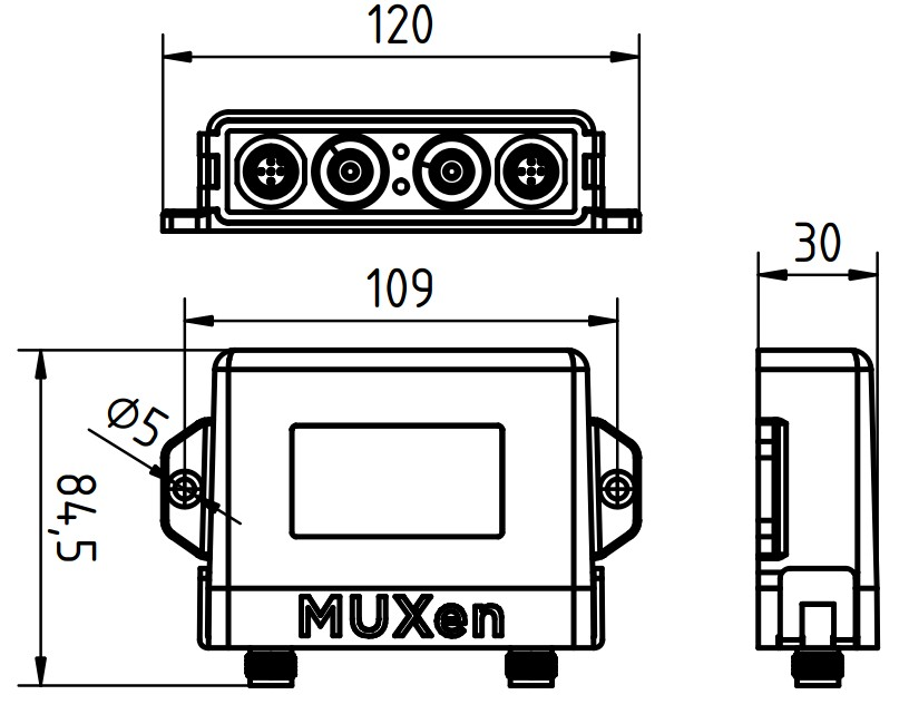
Dimensions: 120 × 84.5 × 30 mm, mounting hole spacing 109 mm, Ø 5 mm.
Installation constraints:
- Install protected from direct spray and any risk of immersion.
- Mount vertically (connectors facing down) or horizontally.
- Fix with two M4 countersunk screws (not supplied).
- Leave at least 70 mm of clearance below the housing for cable routing.
- All output cables must be properly secured — the housing must never bear cable weight.
Operation and configuration
The primary purpose of a CAN-CAN is to convert a third-party protocol (e.g. NMEA 2000) into the MUXEN standard. Once connected, the gateway registers itself on the MUXEN network as as many devices as it discovers on the third-party bus.
Example: a CAN-CAN connected to a Victron VE-CAN network with one Lynx BMS and 2 Quattro inverter/chargers will appear on the MUXEN network as 1 battery + 2 inverter/chargers.
The behaviour of a CAN-CAN therefore depends heavily on the equipment connected to it.
In addition, every CAN-CAN exposes at least one Genio-type device on the MUXEN network so its I/Os can be used. Configuration parameters of this Genio function:
| Parameter | Description |
|---|---|
InstanceNum | Network instance of the unit (0..63) |
EnAnalogPwr | 0 — analog input supply disabled1 — analog input supply enabled |
EnGenIo | 0 — generic-IO frames not emitted1 — generic-IO frames emitted |
EnCanAuxPwr | 0 — third-party bus +12 V supply disabled1 — third-party bus +12 V supply enabled |
Relay1Eqn | Trigger equation for relay 1 (see equation reference document) |
Relay1Latch | 0 — relay 1 momentary (follows trigger)1 — relay 1 latched |
Relay2Eqn | Trigger equation for relay 2 |
Relay2Latch | 0 — relay 2 momentary1 — relay 2 latched |
Relay modes
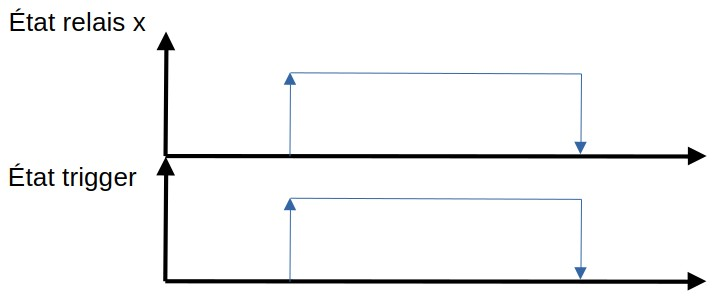
- Momentary (
RelayXLatch = 0) — the relay state mirrors the trigger state: it activates when the trigger goes high and releases when the trigger goes low. - Latched (
RelayXLatch = 1) — the relay toggles on each trigger pulse: a first pulse activates it, a second pulse releases it.
RelayXLatch = 0 (momentary)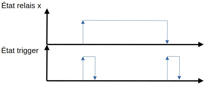
RelayXLatch = 1 (latched)Wiring (Full version)
The Full version is wired with three connectors:
- Orange (MUXEN bus) — daisy-chained on the MUXEN network via a T-junction.
- Blue (third-party bus) — daisy-chained on the third-party CAN network via a T-junction.
- Green (I/O, Amphenol AT16-18) — analog inputs, digital inputs and relay outputs.